
White Papers
Rapid development for launch of a complex positioning system
Introduction
Positioning stages capable of micron-scale accuracy, repeatability, straightness, and flatness play essential roles in applications ranging from life sciences to semiconductor fabrication. Unfortunately, developing stages with this level of performance can be difficult and time-consuming. Translating design will volume production can be even harder. This is a problem, because delaying time to market by even a month can significantly impact profitability over the lifecycle of a product.
A biotech company learned that lesson the hard way when it discovered that the complex multi-axis positioning system in its marquee DNA analyzer didn’t perform as required. To solve the problem, the company turned to Motion Solutions. Our finely tuned processes, comprehensive design portfolio, and in-house expertise equip us to greatly compress the time needed to take a project from design through volume production. In the case of the biotech company, we delivered a stage that exceeded their specifications and ramped up manufacturing to deliver hundreds of units annually in a fraction of the typical time (see Figure 1).
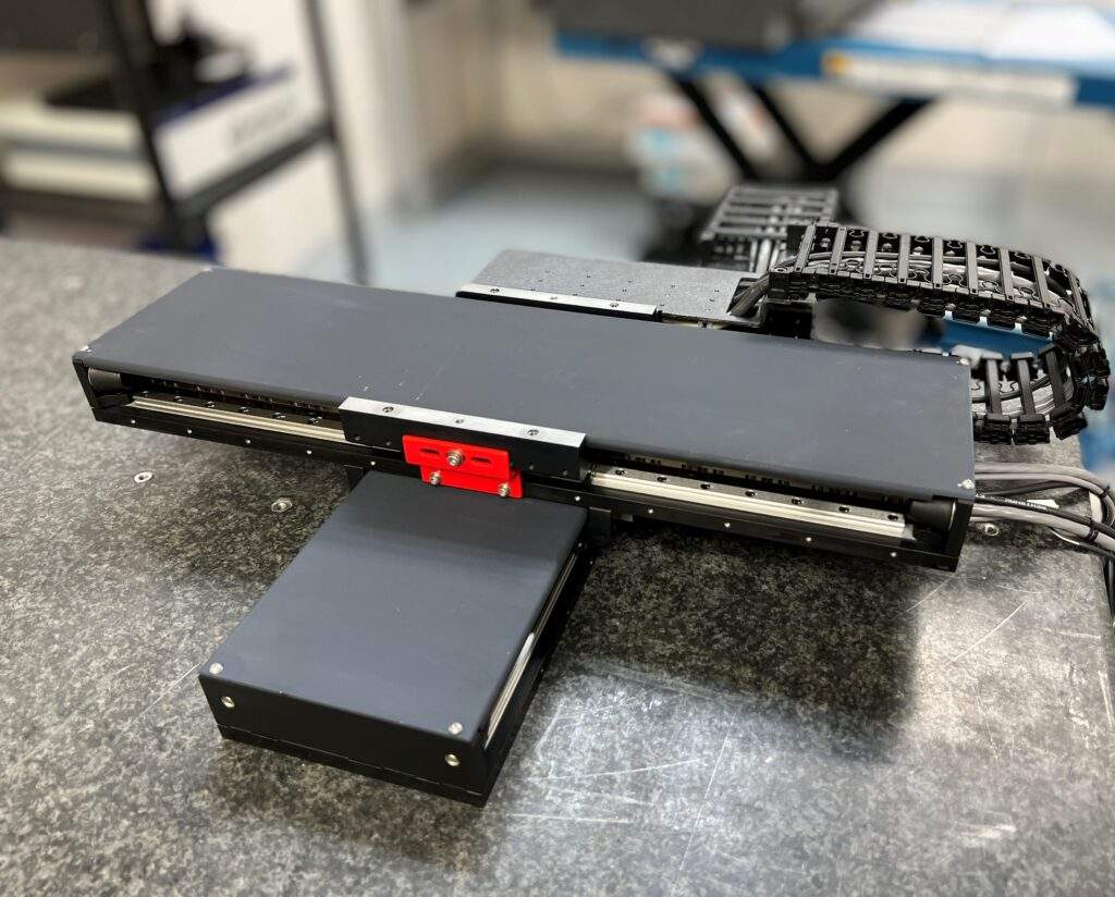
Figure 1: The Motion Solutions Phase-Gate Process enabled us to design a drop-in replacement for a customer that outperformed their previous vendor, moving from design through volume manufacturing in a fraction of the time normally required.
The project
The project consisted of a multi-element linear positioning system to replace the stage that the OEM was currently using. The system consisted of:
- An XY stage capable of step and settle moves to position the sample underneath the sensor
- A Z-focus stage to ensure an in-focus image for an accurate reading
- A linear stage to position ancillary components within the instrument
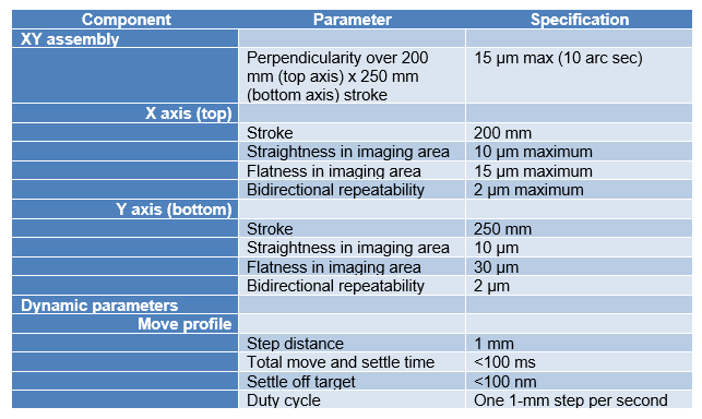
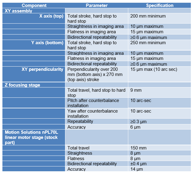
The XY stage, in particular, had to perform with micron-scale repeatability, as well as strict levels for flatness and straightness (see Table 1).
Because the stage was needed for an existing instrument, the new design also had to be a drop in replacement for the existing solution. The instrument was already on the market, so there was also significant pressure to move the stage through design and into production as rapidly as possible, with a target production of hundreds of units annually.
Table 1: Customer specifications
The process
When Motion Solutions began offering engineering services, we used product lifecycle management (PLM) theory as our jumping off point. We quickly realized that the five stages of a conventional PLM model – design, development, production, support, and retirement – were insufficient for the development of high precision motion systems.
Over decades of work and thousands of projects, we established and refined our own five-step methodology that we call the Phase-Gate Process. We identified pinch points and refined our process to eliminate them. For example, we include checks and balances at every stage to ensure that we meet specifications. We obtain customer approval at all critical decision points so that there are no surprises. We’ve broken down silos across the company, allowing us to expedite the process without rushing.
Because Motion Solutions also has a distribution business, we have the added benefit of decades-long relationships with key suppliers and a deep familiarity with their products. This has historically stood us in good stead when it comes to getting projects out the door quickly.
Phase 1: Project Planning
Planning provides the foundation for success. This is where we gather requirements and consider the feasibility, particularly in the context of budget and timing. We designate a project lead and the design team members.
Phase 2: Preliminary Design
The success of a product depends on the quality of its design. It’s easy to make a prototype that works in the lab – our specialty is meeting customer specifications with designs that can be manufactured in volume, while meeting budget and schedule. How do we do this quickly and accurately while maintaining quality? We’ve been building stages for 20 years. We’ve amassed a portfolio of reference designs and a toolkit of techniques for attacking the most challenging requirements. As a result, we’re not reinventing the wheel every time. Instead, we leverage our pre-existing knowledge base to efficiently arrive at the best solution for each project.
In the preliminary design phase, we collaborate with the customer to lock down design requirements. We draw on our portfolio to develop a top-level design concept. With our history, it’s likely that we’ve built something similar in the past. If not, our expert engineering team will develop a clean-sheet design, using our proven techniques to optimize performance.
Once we have our concept, our cross-department collaboration begins. At the end of this phase, we conduct a preliminary design review with in-house teams and the customer to keep everyone informed and identify any issues.
Phase 3: Detailed Design
In this phase, we convert our concept into a complete design. We develop detailed CAD models and conduct thorough engineering analyses using sophisticated modeling techniques like finite-element analysis (FEA). Bearings, for example, are modeled as dynamic elements, not just static, rigid elements. This more accurately accounts for their effect on the overall performance of the system.
At this point, several steps take place in close succession. We conduct a risk analysis, never losing sight of our top-level planning parameters. We hold a critical design review with the participation of the entire cross-disciplinary team to validate all aspects. At this point, we bring in the customer for design approval.
Now, we can generate a bill of materials (BOM) to finalize costing, part numbers, drawings, etc.
Phase 4: Prototyping
The prototyping phase is where we begin to reap the benefits of the previous steps. We finalize drawings and generate data sheets. We initiate preliminary release to the PLM system, which gates internal approvals.
One of the keys to ramping up quickly is our integrated procurement process. Material requirements planning (MRP) software enables us to establish a master project schedule and break it into detailed steps. We can use MRP to manage procurement throughout the design cycle to ensure that necessary components and material are in house when it’s time to move into prototyping and production. We can use the BOM to identify components with long lead times so that our production department can begin reaching out to the supply chain, for example. The benefits of this digital tool continue through volume manufacturing, making sure that inventory is replenished in a timely fashion.
Our extensive design work and modeling in Phase 3 minimizes the need for major design revisions during prototyping. Any minor adjustments can be accelerated by our in-house processing capabilities, which include:
- An on-site machine shop to quickly fabricate precision parts
- A library of balls to fine-tune bearing preloads
- On-site cleaning capabilities for changing lubrication
These capabilities enable us to machine specialty parts from scratch. We can modify stock components like linear bearings rather than facing the lead time of ordering a custom-built unit from the manufacturer.
Once we’re satisfied with the prototype, we perform validation and lifetime testing. The final step is to meet with the customer to present results and obtain acceptance. This is generally pro forma, since we’ve kept them informed throughout the process.
Phase 5: Production
For some vendors, releasing a prototype to production is a major step. With our Phase-Gate Process, moving to production is more of an evolution. The performance has been validated and approved by the customer. We have a complete design file that we can turn over to production. Just as important, vendor selection and cost reduction have been underway since the BOM was released in Phase 4.
Phase 5 starts with initiating production release to PLM (internal approval gate). We develop manufacturing documents such as assembly procedures and inspection sheets. Our facility is ISO-13485 certified, so the groundwork has already been laid, including procedures in place for implementing changes and revisions. The combination helps us to move rapidly into full-scale production. We have a robust supply chain and leverage our MRP and ERP tools to ensure that materials are available when they’re needed.
Assembly is the responsibility of our team of skilled technicians, Mark who have experience building thousands of units of precision equipment per year. With $3.5 million in capital equipment, we have the tools and test and inspection equipment already in place to run many projects simultaneously. Taking a new stage design and ramping up to full production is really just a matter of adapting existing equipment and procedures to the specifics of that new project.
Production is where the techniques of design for manufacturing bear fruit. Elements incorporate alignment features, we build specialty test fixtures for verification testing, and organize the production line to maximize throughput. All of this helps streamline assembly.
Engineering trains staff for the initial five to 10 units of production. To guarantee quality, we have a comprehensive inspection sheet developed with the customer during Phase 5. We test 100% of units during assembly, followed by final QA inspection. We also offer vibration testing by an outside lab if requested by the customer.
Challenges
To demonstrate how our Phase-Gate Process helps us accelerate from design through volume production, let’s take a look at how we used it to make the positioning system for the DNA analyzer a success.
Footprint
We used linear motors for the XY stage and a voice coil motor for the Z-focus stage. Both the XY stage and Z focusing stages were based on well-established base designs from our portfolio of successful projects. We used these as our starting points, applying a variety of techniques established during Motion Solutions’ decades as a developer of precision motion systems. Working with the customer very early on in product development enabled us to optimize the design to perfectly fit what they needed.
The hardest part was building a positioning system that would outperform the existing system but fit in the same space. Using a thin baseplate helped lower the profile, but it created a new issue in meeting specs for flatness and straightness.
Because the X axis is perpendicular to the Y axis, the load would introduce a deflection at the extremes of travel that could degrade image quality. We mitigated this risk by increasing stiffness using high precision linear bearings with proper bearing design.
Linear motors with low profiles
The linear motors that drive the XY stages must be powered directly. This means the cables flex with every cycle. Because of our limited envelope, we used low-profile stages, which made the bend radius even smaller. The smaller the bend radius, the lower the lifetime of the cable.
In the engineering phase, we put a concentrated effort into cable design. We started with custom high-flex cables. We built test fixtures to run the cables through lifetime testing to ensure that they were going to last. Validating the cable was an important step that took place in parallel with other design tasks.
Extreme flatness requirements
Achieving the specification of 5.1 µm over 200 mm required high-precision manufacturing. To ensure quality, we developed a specialized test fixture to measure straightness and flatness in this area. Our capital equipment includes a dedicated test lab with multiple laser interferometers. We use them repeatedly to confirm accuracy and repeatability.
Short settling times
The dynamic requirements for the Z-focus stage were particularly demanding. The move profile was 500 nm, with a settling time of less than 10 ms. It’s a common misconception that settling time is purely a function of controls and feedback. In reality, the mechanical design has a major impact on settling time, as well. The same bearing techniques that optimized stage stability also helped with dynamic performance.
Tight schedule
In the case of the third stage required for positioning of additional components, we were able to use a stock nPL70L linear motor stage from the Motion Solutions families of precision positioning stages (see figure). We initially developed these stages for use in customer’s custom engineering by our custom engineering team when we were unable to find commercially available alternatives. At the request of customers, we made them available as highly configurable stock items.
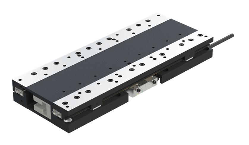
Figure: The nPL70L linear motor stage positions with bidirectional repeatability of ±0.4 µm and straightness and flatness of 8 µm over a maximum travel of 150 mm.
In the case of this project, the nPL70L was ideal for the additional axis, eliminating the need for another custom design and reducing overall cost.
Production ramp up
Table 2 summarizes the specifications on the inspection sheets developed with the customer in the design phase. Note that these specifications in some cases exceed the performance initially requested by the customer.
Table 2: Inspection sheet specifications
Assembling stages with submicron specifications requires a different approach from standard work. Our process is to measure the straightness of each rail as we install it and adjust as necessary. Testing takes place via laser interferometer.
Now consider the larger picture. Each positioning unit consists of three precision subassemblies. Producing 10 units per week, for example, equates to assembling 30 separate high-precision subassemblies, each requiring multiple laser interferometer measurements before integration into the final product, followed by additional acceptance testing.
This testing is essential but also time-consuming. To streamline assembly, we created a work cell specifically for this project on our 36,000 sq ft production floor (see Figure 2). We located the work cell close to our laser test lab to minimize dead time and maximize throughput. This modification paid off when the customer doubled the number of units per week soon after the launch of the project.
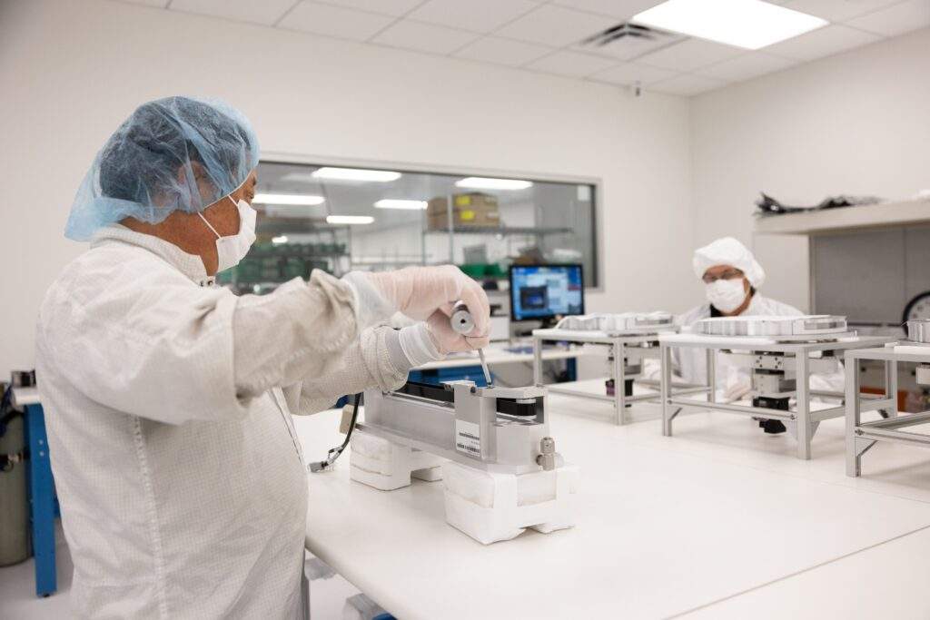
Figure 2: To streamline assembly, we built a dedicated work cell for this project, locating it close to our test lab to minimize the amount of time spent transporting the stages for required confirmation testing after certain assembly steps.
Conclusion
Motion Solutions has a 20-year track record of successfully taking demanding linear positioning projects from design through volume production. We’ve perfected our five-step Phase-Gate Process to eliminate pinch points. As a result, we can accelerate the ramp-up phase without rushing. And with 100% testing, we stand behind our quality. In the project above, we overcame many challenges to meet or exceed all requirements in terms of both performance and schedule. The Motion Solutions Phase-Gate Process, along with our in-house expertise, tools, and equipment, enable us to take on the most demanding projects with confidence.
Have a precision motion challenge you need solved? Reach out to Motion Solutions to discover how we can put our technology, resources, and expertise to work for you.
Categories
- Case Studies
- Company News
- Customer Focus
- Engineering Insights
- Featured Products
- Industry Perspectives
- nPoint Blog
- Our Take
- Product Spotlight
- Uncategorized
More From the Blog

Novanta Acquires Motion Solutions
Novanta Inc. (Nasdaq: NOVT) (“Novanta” or the “Company”), a trusted technology partner to medical and advanced technology equipment manufacturers, announced today that it has finalized a definitive agreement to acquire Motion Solutions, a leading provider of highly engineered integrated solutions.