
White Papers

Hybrid Piezo Gripper Combines High Force with Wide Opening Distance
Introduction
In the macro world, a variety of options exist for precision positioning, such as rotary motors with screw-type actuators or linear motors. At the sub-micron scale, things become more difficult. Conventional approaches present significant performance and environmental barriers. More sophisticated options like air bearings and voice-coil motors introduce problems of their own. For applications requiring ultrafast nanoscale positioning with zero contamination, there’s a special solution set – flexure-based actuators driven by piezoelectric stacks.
Flexure-guided piezoelectric actuators provide a number of advantages for the most demanding precision motion applications. They can achieve sub-nanometer resolutions over up to a millimeter of travel. With proper feedback, they can be extremely repeatable. Because these actuators don’t incorporate conventional bearings, the approach eliminates most points of failure and maintenance requirements. This combination of characteristics makes them extremely effective for applications like fiber alignment, super resolution microscope objective focus, wafer inspection, and other tasks in aerospace, life sciences, optics and photonics, and semiconductor fabrication. Here, we review key characteristics and design considerations for flexures and piezoelectric materials, illustrating with a flexure-guided monolithic piezoelectric gripper capable of 13 N of grip force and a total jaw travel of 1.6 mm.
What are piezoelectric materials?
Piezoelectric materials are ceramics that expand and contract under an applied voltage. They can be used to generate force and displacement in motion applications.
Benefits
Piezoelectric materials offer a number of advantages for motion applications. They operate with spatial resolutions on the order of hundreds of picometers, and in closed-loop operation with highly accurate sensors, motion is highly repeatable. Piezoelectric materials have very fast response times. They don’t require internal bearings, which eliminates points of failure. Lack of bearings also means that piezoelectric stacks don’t need lubrication and they don’t generate particulates, making them especially suitable for vacuum applications.
Challenges
Piezoelectric materials do have certain characteristics that require informed use. They have inherent hysteresis. The effect can be as high as 5% of expansion. As a result, repeatability for open-loop operation in bidirectional applications is very poor. This can be significantly improved with the addition of high-resolution closed-loop feedback.
Another issue is that the amount of expansion is only a fraction of a percentage of the material thickness. To increase expansion, piezoelectric actuators are typically fabricated as laminar structures formed of stacks of thin piezoelectric plates. The expansion of each plate is small, but displacement is additive. That said, total displacement of a typical stack is still only on the order of 1 to 2 µm/mm for a 180-V voltage differential. To increase travel, we apply a mechanical solution – flexures.
Flexure-based actuators
A flexure is a type of mechanical guidance system that enables motion through elastic deformation. As such, it has significant advantages for high-resolution, high-performance positioning. Most bearings are based on sliding or rolling contact. Each surface features nonconformities at the micrometer scale, causing friction, stiction, and inaccuracy in running parallelism. These surface defects change with every pass, compromising repeatability and generating particulates. Particulates create issues for vacuum or contamination-sensitive environments. They are also a symptom of wear and progress toward eventual failure.
Flexures, in contrast, are completely noncontact. As a result, they do not introduce friction or stiction. They don’t generate particles and are highly repeatable.
Properly designed to limit the degree of deformation, flexures are very robust, with long lifetimes. Even when compared to other non-contact bearings like air bearings or magnetic bearings, flexures offer advantages such as reduced complexity and smaller form factors.
Flexures range from very simple, blade-like designs (see Figure 1) to complex versions capable of motion along multiple axes and angles of rotation. Depending on size and complexity, they can be fabricated using precision machining, electrical discharge machining, or lithographic patterning.
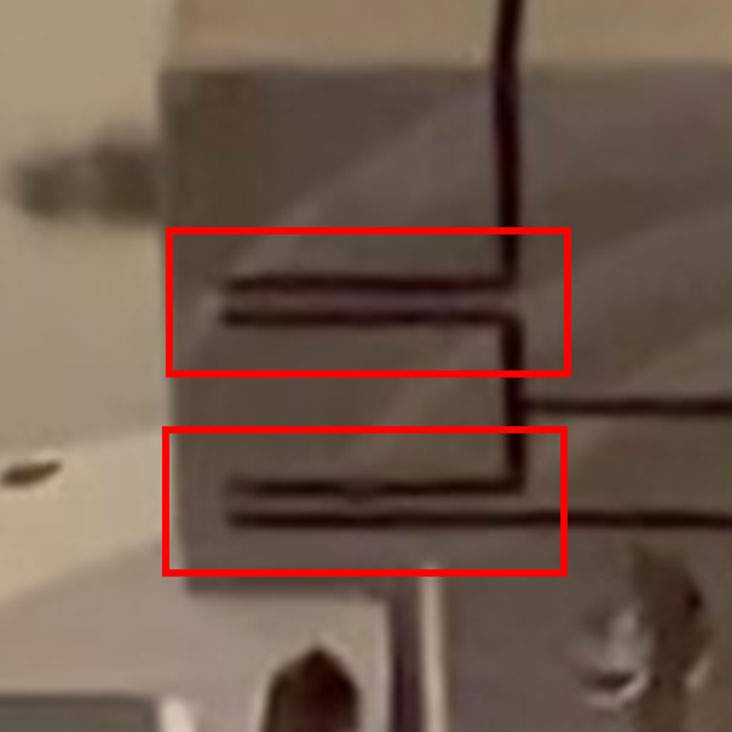
Figure 1: Cuts machined in a monolithic block of metal define individual bodies connected by flexures (red rectangles). Elastic deformation of the flexures enables the bodies to move with respect to one another to perform specific tasks.
Flexures provide a solution for some of the challenges of piezoelectric materials. They can be used to significantly amplify the motion of the piezoelectric stack. The Motion Solutions nPFocus1000, for example, can provide up to 12X amplification (see Figure 2). Flexures offer many design options for redirecting the force generated by a piezoelectric stack into different axes and/or angles of rotation – often simultaneously. Let’s take a closer look at some of these capabilities.
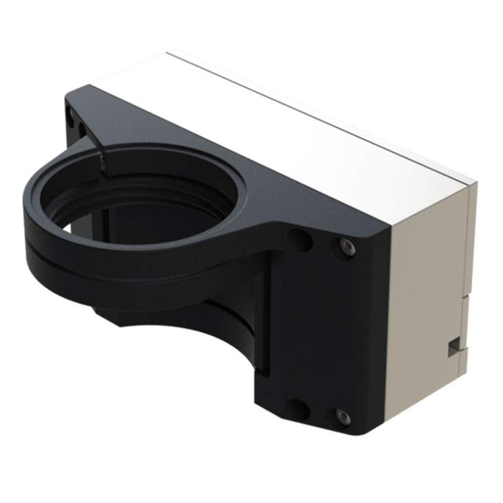
Figure 2: The Motion Solutions nPFocus1000 uses flexures to amplify piezoelectric expansion by a factor of up to 12X amplification, for a maximum closed-loop travel of 1000 µm.
Amplification
For our discussion of amplification, consider the previously mentioned example of a piezo-driven gripper. The gripper jaws need more than 1 mm of total travel while remaining parallel. Let’s start with the use of a flexure to amplify the displacement introduced by a piezoelectric stack (see Figure 3). In this simple design, a piezoelectric stack applies a force to a rigid L-shaped structure. When the piezoelectric stack expands, the flexure causes the structure to pivot, amplifying the piezoelectric displacement.
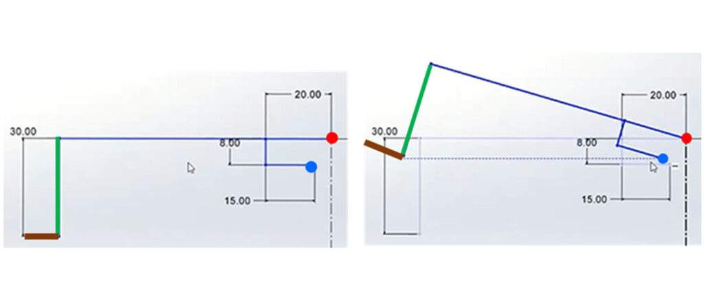
Figure 3: Model simulates the forces involved in a simple piezo-driven flexure amplifier. The piezoelectric stack applies force at the blue dot, while the elastic deformation of the flexure supports rotation at the red dot. The amplification is substantial but note that the end face (green) and gripper jaw (brown) tilt with the motion. [NOTE: This is not an accurate rendering of a flexure, just a diagram of forces and displacement.]
Parallelogram amplifiers
Although the structure shown in Figure 3 provides amplification, it doesn’t meet the project requirements of keeping the jaws parallel. The answer is to use a parallelogram amplifier, a common tool in flexure actuator design.
A parallelogram amplifier consists of a parallelogram with a flexure at each corner (see Figure 4).
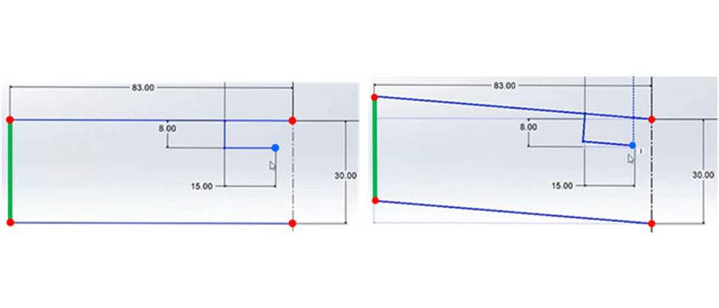
Figure 4: Model simulates the behavior of a parallelogram amplifier. Instead of a rigid L-shaped member, the structure consists of four rigid elements connected by flexures (red dots). When the piezoelectric stack expands to apply a force (blue dot), the displacement of the end face (green) is amplified but the member remains vertical (right). [NOTE: This is not an accurate rendering of a flexure, just a diagram of forces and displacement.]
The parallelogram amplifier is a good solution for our gripper application. Because the end face of the parallelogram is constrained by the other members of the parallelogram, but the constituent parts are free to move, the end face remains vertical. As a result, the gripper jaw connected to the base of the end face will remain horizontal over the range of travel.
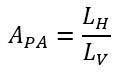
We can express the amplification of a parallelogram amplifier APA by:
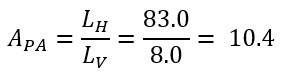
where LH is the horizontal lever arm and LV is the vertical lever arm. For the system modeled in Figure 4, amplification is given by:
Angled flexure amplification
The parallelogram amplifier amplifies motion while maintaining the orientation of the end face. Angled flexures provide a method for extending travel.
In an angled-flexure amplifier, the flexure transfers motion to the parallelogram at an angle (see Figure 5). In addition, it connects to the parallelogram at the base. The combination increases the degree of amplification.
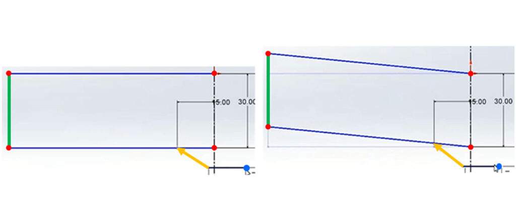
Figure 5: In an angled-flexure amplifier, force generated by the piezoelectric stack (blue dot) is transferred to the parallelogram structure by an angled flexure (yellow arrow).
Piezoelectrics and flexures in action
To demonstrate the use of the technologies, let’s return to our gripper example. The goal was to develop a device for semiconductor applications that would meet the following objectives:
• High grip force
• A high level of control for delicate materials
• Precision motion during load acquisition and closing of jaws
• Ability to open at least 1.5 mm
• Fail to closed position when unpowered
• Small footprint – most equipment is space limited
• Vacuum compatible – many processes take place in vacuum, which constrains materials, lubricants, and the assembly process
The solution – a flexure-based piezo gripper with dual amplification
Based on the discussion above, let’s go through the design process, highlighting the benefits and challenges of working with the two technologies and how we address them for this application.
The motor
We started with a piezoelectric stack (our piezo “motor”). Piezoelectric stacks maintain stiffness when unpowered. In contrast, voice coil motors require external brakes that add cost, complexity, and points of failure. Linear actuators can be self locking, but they need encoders and lack the precision this type of application needs. Both conventional solutions generate contaminants that present challenges in vacuum environments, whether just particulates (voice-coil motor) or particulates and lubricants (linear actuators).
The ability to retain stiffness without power also simplifies control-loop tuning. Generating stiffness through force requires constant adjustment as the dynamics of the system change. In the case of piezoelectric actuators, stiffness along the axis of motion is inherent to the material, so control-loop tuning becomes quite a bit simpler.
Motion and amplification
To achieve the required jaw travel, we applied a dual-amplification flexure design. We used parallelogram amplifiers to keep the jaws parallel. We added angled flexures to each jaw to increase amplification. The design may sound simple, but it requires thorough knowledge of load parameters and system dynamics. To fully characterize the interactions of the two flexure systems, we made extensive use of finite element analysis. The resultant structure gave us a total jaw separation of 1.6 mm.
Precise control of force
The application demanded very precise force control, but the form factor of the device was too small to measure it directly. The size of the load is known and very consistent, however, so we calibrated the system to the specified force. The approach is simple in theory, but the devil is in the details. Our engineering team was able to bring to bear extensive experience with flexure-based piezoelectric actuators to maintain very precise control of force.
Managing resonance
Resonances can limit the ultimate speed and usability of a positioning system. The ideal approach is to push the resonant frequency of the system as high as possible, then use filters in the control system to avoid exciting resonances. This is where the use of a piezoelectric actuator pays dividends. Recall, piezoelectric actuators are very stiff, giving them a high resonant frequency. We optimized the mechanical design to maximize the full assembly resonant frequency for the given form factor and travel requirements.
The results
The use of piezoelectric actuator and hybrid flexure design resulted in a gripper that not only met but exceeded specifications. The final performance of the system was:
• Maximum travel between jaws: 1.6 mm
• Total grip force: 13 N
• Lifecycle per accelerated lifetime testing: greater than 175,000 grip and transfer cycles
Conclusion
Piezoelectric actuators and flexures can be used to build very effective precision motion devices. They’re most suitable for applications requiring resolutions of 10 nm or less over 1 mm of travel or less. Because they are noncontact devices, they don’t require lubricants or generate particulates, making them ideal for vacuum environments. The lack of contact also gives them extremely long service lives.
Our team at Motion Solutions has a long track record of success designing and fabricating piezo-driven flexure actuators for a variety of applications. The Piezo Gripper was a successful clean-sheet design developed entirely by our specialists. Find out how we can assist with your next project.
What to Know Before You Call
- Axes of motion
- Range of motion (in x, y, and z)
- Footprint (length, width, height, aperture)
- Preferred materials
- Max load (g)
- Operating speed
- Resolution (nm)
- Environmental requirements
- Application
Categories
- Case Studies
- Company News
- Customer Focus
- Engineering Insights
- Featured Products
- Industry Perspectives
- nPoint Blog
- Our Take
- Product Spotlight
- Uncategorized
More From the Blog


Novanta Acquires Motion Solutions
Novanta Inc. (Nasdaq: NOVT) (“Novanta” or the “Company”), a trusted technology partner to medical and advanced technology equipment manufacturers, announced today that it has finalized a definitive agreement to acquire Motion Solutions, a leading provider of highly engineered integrated solutions.