Editor’s Note: This blog post is part of a series of occasional articles featuring guest authors from among our partners.
Gantries play an important role in a variety of applications such as DNA analysis, pick-and-place assembly, industrial materials handling, and many others. Gantries require tight coordination between two axes. Even small differential following errors can cause binding that can reduce accuracy, cause uneven motion, and even stop the gantry from moving altogether. Specialty drives that incorporate gantry-specific features can help prevent these issues while streamlining design and commissioning.
Improving gantry performance
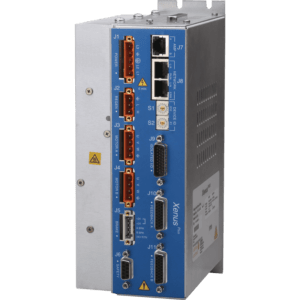
Gantries are often operated with either centralized control (PLC or motion controller) or distributed control (master-slave architecture). The problem is that both options introduce latency. Dual-axis drives provide a more effective solution. In a dual-axis drive, the signal for both axes is transmitted simultaneously for latencies on the order of a few hundred nanoseconds (see figure 1).

There are several techniques for improving accuracy and minimizing binding in gantries. We list them below in order of increasing accuracy and effectiveness.
- Method 1: Simply synchronizing clocks and commanding both axes to the same position at the same time can prevent binding. This technique can be used with independent motor drives, although it is not effective for applications with high speed or accuracy requirements. Dual-axis drives deliver better performance.
- Method 2: Cross coupling can be used in a mechanically loose system to make the axes follow each other. The error from axis #1 is fed to axis #2, causing axis #2 to modify its speed in order to coordinate motion with axis #1 (see video below). The result is increased accuracy and minimal levels of binding.
Cross Coupling with a Copley 2 Axis Drive Video
Although the technique can be used with centralized control and distributed control, both approaches introduce latency. Cross coupling with a dual axis drive allows automated tuning algorithms to match the performance of one axis to another, as this video shows.
- Method 3: Parallel control motor currents can be used in mechanically stiff systems that suffer from fighting axes. Stiff gantry systems will inherently fight each other due to encoder/mechanical position error as read by the two drive axis. This especially shows up with integral gain and can cause full current with one axis pushing in the forward direction while the other is pushing in reverse.
- Method 4: Encoder corrections can improve accuracy between axes over a distance, increasing accuracy and reducing binding due to error.
When properly matched to the application, the techniques above can be very effective. Several of them can be challenging to execute, however. To simplify implementation, encoder corrections are available on all Copley Controls Plus-featured FPGA processor-based drives.
Error-correction tables
The quality of positioning control that a servo drive can achieve is limited by the resolution and accuracy of the encoder data. Encoder errors can be divided into intrinsic errors introduced during the manufacturing and assembly (e.g. code-disk errors, electronics nonlinearities, decentration, etc.) and errors introduced during installation (e.g. decentration of code disk and detector). One strategy is to measure the encoder errors and generate a table of compensation values that the drive can apply to correct for these errors in real time. This is the method implemented in Copley drives.
The encoder table is a binary formatted file that is uploaded to the internal file system of the Copley dual-axis drive. This file consists of a short header section followed by a list of offsets that will be added to the position information read from the encoder. The resulting values (position from encoder plus offset) will be used in place of the position data read from the encoder. This allows the drive to compensate for known errors in the encoder position data. The position adjustment is linearly interpolated from the contents of the file and the result is added to the original position from the encoder.
The error correction table can reduce following error significantly. As an example, a linear motor stage with 350mm travel that had repeatability of +/-2 µm, but an accuracy over travel of 130um, was compensated such that the accuracy followed the repeatability of +/-2 µm. To be effective, however, the update rate of the error feature needs to match the speed of the gantry. Although the technique can be used with centralized or distributed control, those architectures introduce communications latency. In Copley’s dual-axis drives, the encoder error correction is executed in the firmware. As a result, feedback is corrected within the drive at the position loop update rate of 250 µs.
Performing error correction in the dual-axis drive brings another benefit which is that error correction is applied to both axes to within a few hundred picoseconds. The dual-axis drive exhibits lower jitter and faster update rates than either centralized or distributed control.
Gantries play essential roles in motion systems across a wide variety of applications. The techniques described above can make a significant difference in the performance of the motion system. By taking advantage of the built-in features of Copley drives, along with engineering services and support from Motion Solutions, OEMs can optimize motion performance while focusing their own engineering efforts on product features that give them a competitive advantage.
About the Authors

Dean Crumlish is product manager and senior applications engineer at Copley Controls.

Bill Lackey is vice president of automation, Motion Solutions.


